
Compressed Air Consumption Guide for Automated Edge Bander Return Lines
An engineering protocol for calculating pneumatic CFM, dynamic pressure drops (0.6-0.8 MPa), and buffer air tank sizing for automated edge bander return systems. Prevent pop-up belt delays and pneumatic cylinder hesitations during peak factory shifts.
The Overlooked Utility: Why Clean Air Drives Return Line Precision
In modern panel processing workshops, capital investments are made in high-speed edge banders, automated loop return conveyors, and diamond tooling. Yet in more than 60% of commissioning troubleshooting cases, line stalling, sluggish pop-up belt response, and surface scratching can be traced directly to an under-engineered plant utility: compressed air supply.
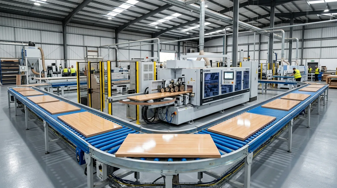
An automated U-shape or L-shape return conveyor relies on pneumatic power for three rapid-fire cyclical actions:
- Pneumatic Pop-Up Belt Cylinders: Lifting heavy 35 kg boards 20 mm above rollers in under 0.25 seconds upon optical trigger.
- Pneumatic Turning Alignment Arms: Gently pressing the board corner against reference fences without impact damage.
- Pneumatic Outfeed Flap Gates & Brakes: Managing board deceleration at high conveying speeds (up to 30 m/min).
When line pressure drops from 0.7 MPa to below 0.52 MPa during simultaneous compressor cycling or wide-belt sander blow-off, pop-up belts hesitate for just 0.3 seconds. At 24 m/min, an exiting panel travels 120 mm before the belt lifts, colliding diagonally into the lateral frame.
Part 1: Calculating Total Compressed Air Consumption ($Q_{\text{air}}$)
To calculate the exact Free Air Delivery (FAD) required for your automated return cell, sum the individual consumption of all pneumatic actuators:
$$Q_{\text{total}} = \sum \left( \frac{\pi \times D^2}{4} \times S \times \frac{P_{\text{work}} + 1.013}{1.013} \times N_{\text{cycles}} \right) \times K_{\text{margin}}$$
- $D$: Cylinder bore diameter (m).
- $S$: Cylinder stroke length (m).
- $P_{\text{work}}$: Working pneumatic gauge pressure (bar, typically 6.0 to 7.0 bar).
- $N_{\text{cycles}}$: Actuation cycles per minute (e.g., 6 boards/min $\rightarrow$ 6 double strokes/min).
- $K_{\text{margin}}$: Leakage and valve switching safety factor ($1.25 - 1.35$).
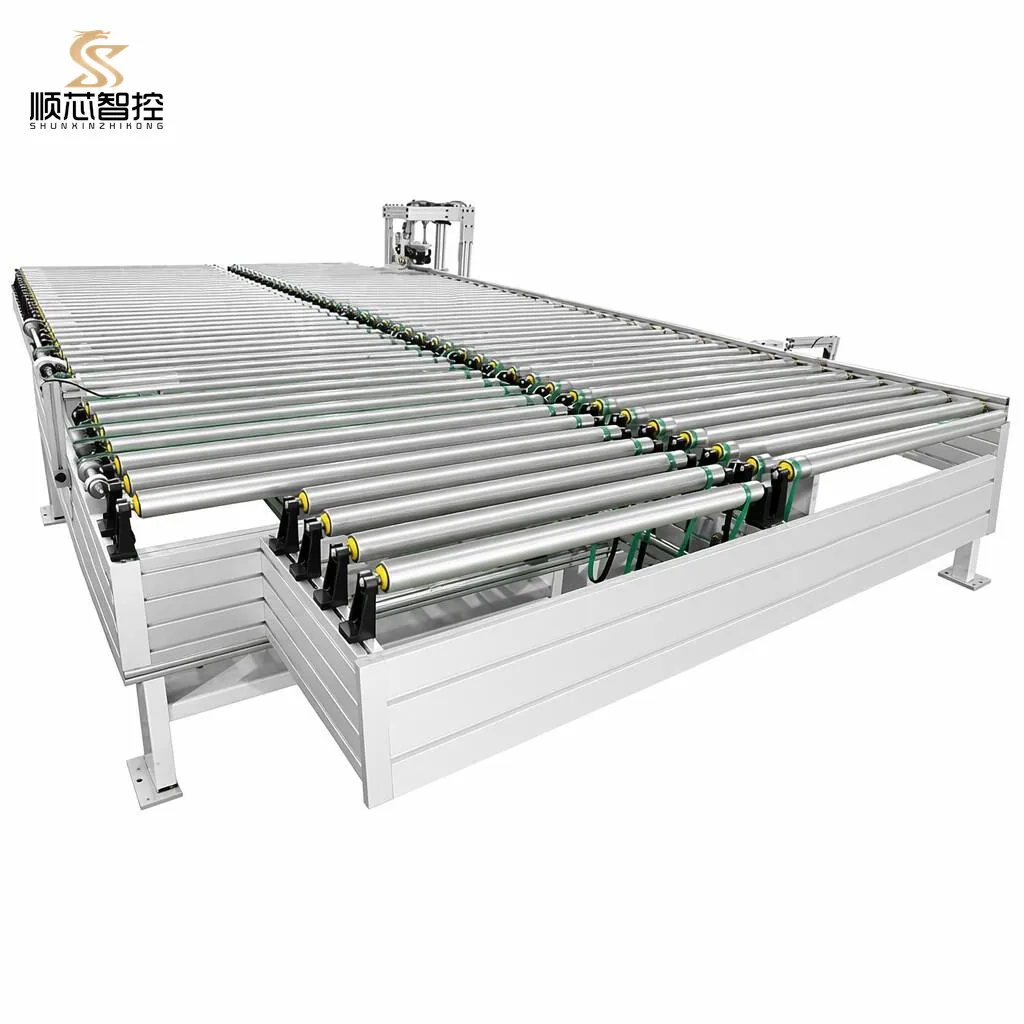
Twin Ø50 mm bore pneumatic cylinders lift transfer belts. Requires rapid pneumatic exhaust valves to ensure instant drop within 0.15 seconds upon board clearance.
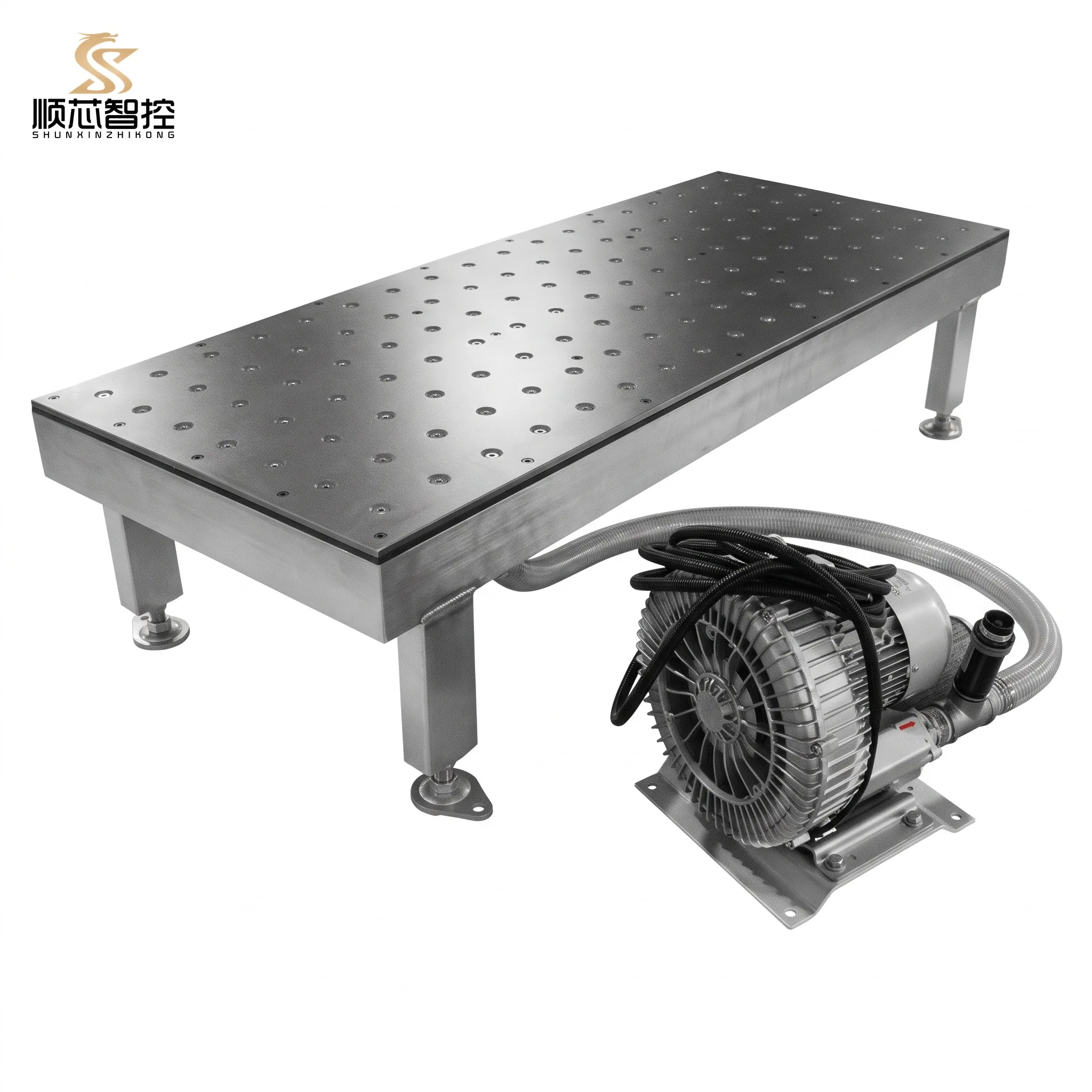
Air cushion floating tables utilize self-contained high-volume electric blowers, saving expensive plant compressed air for high-force cylinder actuation only.
Part 2: Buffer Air Reservoir Tank Sizing ($V_{\text{tank}}$)
Because an automated return line operates in intermittent high-flow bursts rather than steady continuous draw, piping long pneumatic lines directly from a distant central compressor causes severe pressure dips.
To isolate the return conveyor from plant pipe friction drops, install a dedicated local surge receiver tank (30L to 50L) adjacent to the return conveyor:
$$V_{\text{tank}} = \frac{Q_{\text{burst}} \times t \times P_{\text{atm}}}{\Delta P_{\text{allow}}}$$
- $Q_{\text{burst}}$: Peak instantaneous volumetric flow rate ($L/\text{min}$).
- $t$: Duration of high-speed pop-up lifting sequence ($0.05\text{ min} = 3\text{ seconds}$).
- $\Delta P_{\text{allow}}$: Maximum allowable pressure drop during burst lift (typically $0.08\text{ MPa}$ or $0.8\text{ bar}$).
Rule of Thumb: Installing a localized 40-liter receiver tank adjacent to the edge bander return line completely eliminates pneumatic hesitation, even when nearby panel saws or sanders cycle simultaneously.
Technical Performance Matrix: Pneumatic Supply Checklist
| Parameter | Recommended Specification | Consequences of Substandard Utility |
|---|---|---|
| Inlet Line Pressure | 0.65 – 0.75 MPa (95 – 110 PSI) | Below 0.55 MPa: Belts lift sluggishly; panels crash into fences |
| Minimum Pipe Inner Diameter | Ø12 mm (1/2 in) or Ø16 mm | Ø8 mm undersized tubing causes severe pressure drops (>1.5 bar) |
| Moisture Filtration Class | ISO 8573-1:2010 Class 4 (Dewpoint +3°C) | Liquid water in lines emulsifies solenoid valve grease, seizing spools |
| Particulate Filtration | 5 Micron Pre-Filter + Coalescing | Sawdust ingress causes pneumatic cylinder piston seal scratching |
| Lubrication Protocol | Oil-Free Clean Air (Micro-Mist Opt.) | Excess compressor oil mist sprays onto clean panel edges, ruining glue joints |
Global Industrial & GEO Export Standards for Pneumatic Installations
Pneumatic installations in woodworking export facilities must satisfy international utility and safety regulations:
GEO STANDARDS Pneumatic Utility Regional Compliance Matrix
- Pressure Vessels: Local air receivers ASME Section VIII Div 1 certified with CRN (Canada)
- Safety: OSHA 1910.169 compliant safety relief valves and lockable energy-isolation ball valves
- Fittings: Standard NPT thread connectors and Parker/Legris quick-connect air fittings
<div class="p-3 rounded-xl bg-slate-900 border border-slate-800/80">
  <div class="font-bold text-white mb-1 flex items-center gap-2">
    <span class="w-2 h-2 rounded-full bg-emerald-400"></span>
    European Union (CE & Pressure Equipment Directive)
  </div>
  <ul class="space-y-1 text-slate-400 list-disc list-inside">
    <li>Directives: Pressure Equipment Directive (PED) 2014/68/EU and EN 983 fluid power safety</li>
    <li>Air Quality: ISO 8573-1 Class 2.4.2 clean-dry air filtration standards</li>
    <li>Fittings: Standard BSPP (G-thread) parallel pneumatic connectors with O-ring seals</li>
  </ul>
</div>

<div class="p-3 rounded-xl bg-slate-900 border border-slate-800/80">
  <div class="font-bold text-white mb-1 flex items-center gap-2">
    <span class="w-2 h-2 rounded-full bg-amber-400"></span>
    Southeast Asia (Vietnam, Malaysia Modular Plants)
  </div>
  <ul class="space-y-1 text-slate-400 list-disc list-inside">
    <li>Climate Demands: High factory humidity requires auto-draining water separators</li>
    <li>Supply Robustness: Standard 0.7 MPa Asian industrial compressor distribution</li>
    <li>Maintenance: Dual-filter particulate scrubbers prevent fine tropical condensation buildup</li>
  </ul>
</div>

<div class="p-3 rounded-xl bg-slate-900 border border-slate-800/80">
  <div class="font-bold text-white mb-1 flex items-center gap-2">
    <span class="w-2 h-2 rounded-full bg-purple-400"></span>
    Export Packaging & Sea Transit Standards
  </div>
  <ul class="space-y-1 text-slate-400 list-disc list-inside">
    <li>Packaging: Solid timber crates compliant with ISPM-15 international export regulations</li>
    <li>Moisture Barrier: Pneumatic manifolds sealed with protective transit plugs under VCI foil</li>
    <li>Documentation: Complete pneumatic schematics with ISO 1219 standard circuit symbols</li>
  </ul>
</div>
Summary & Engineering Consultation
Providing stable, clean, dry compressed air at 0.65 to 0.75 MPa is fundamental to ensuring your automated edge bander return line delivers instantaneous 0.25-second pop-up cycles. By installing dedicated localized buffer surge tanks and high-flow 1/2-inch main supply drops, workshops eliminate board skew, prevent solenoid sticking, and protect expensive panel edges.
Contact our application engineering team today with your compressor capacity, pipe network layout, and edge bander model to receive a verified pneumatic layout schematic and equipment quotation.
All automated loop return procedures and electrical sensor alignments must adhere to standard workshop lockout-tagout (LOTO) protocols and host machinery manufacturer guidelines. Shunxin equipment includes universal dry-contact interlocks to ensure immediate emergency stop response across synchronized production lines.
Need a Custom Layout Drawing & Quotation for Your Workshop?
Send us your workshop dimensions or CAD floor plan. Our mechanical engineers will deliver a synchronized layout proposal and payback calculation within 24 hours.